Ground Penetrating Radar (GPR) Surveys
Ground Penetrating Radar (GPR) Surveys not only reduce environmental risk and testing costs, but also create a safer work environment by providing non-destructive testing for locating materials such as concrete, metal, plastic, and assorted wastes. Federated Environmental’s GPR clients and customers have included commercial lenders, law firms, engineers, surveyors, government agencies, developers, private land owners, land conservation groups, and other environmental companies. Because we do not subcontract our GPR work, our company can offer this service for less than many other companies.
Federated Environmental employs state of the art ground penetrating technology to generate needed information on utilities, buried wastes, and potential obstructions within or under existing structures. Federated Environmental’s GPR Surveys speedily provide both two- and three-dimensional information without any radiation delivery. Federated Environmental’s equipment meets all standard FCC regulations and is properly registered.
A Ground Penetrating Radar (GPR) survey of this HVAC contractor’s location in Rochester, NY cleared the property of underground storage tanks (USTs).
Federated Environmental has recently developed the capability to employ Electromagnetic Induction Technology (EMI) which uses a primary magnetic field to produce an electrical current underground. The underground current produces a secondary magnetic field. The characteristics of the secondary magnetic field reveals the conductivity of soils or rock below. Electromagnetic Induction is best used in open fields or parking lots covered with asphalt.
The broad range of electromagnetic field frequencies available with EMI (with its coupled use with GPR) advances its practical application in professionally supported surveys and like investigations including:
- Geological Mapping (Geological)
- Groundwater Exploration (Hydrogeological)
- Contaminant Detection (Environmental)
- Landfill and Hazardous Waste Site Investigation (Environmental)
- Metal Detection (UST detection, Buried Materials and Wastes)
- Archeological and Forensic (Artifacts, Gravesites)
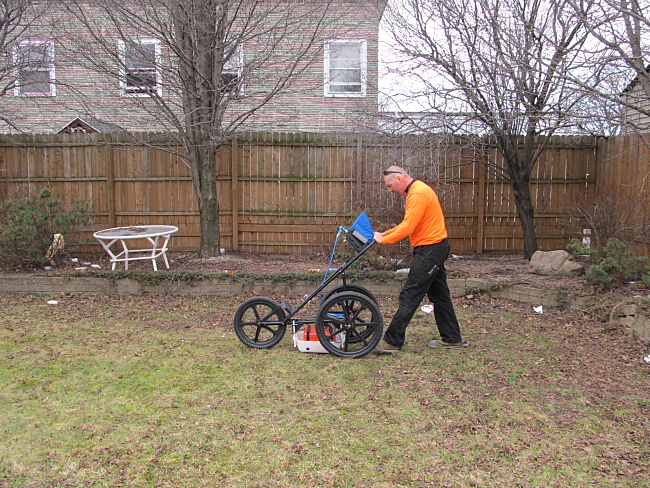
The basic GPR Survey equipment system includes a controller, 400 MHz antenna, survey cart, and cabling. 200, 250, and 400 MHz antennas are the standard antennas for locating utilities, abandoned USTs, shallow geotechnical work, and site assessment projects, e.g. mapping debris, buried drums, drilling obstructions, archeological, forensic, etc. The controller screen illustrates data in real collection time, and permits for file playback and preliminary in-field processing. The GPR Survey software package conducts data processing and analysis, developing 3D maps, report images, and exports for later use in AutoCAD/GIS/Google Earth, and more.
Technical Description of Ground Penetrating Radar (GPR) Technology
GPR technology employs impulse systems that transmit short duration electromagnetic (EM) pulses into the subsurface from an antenna at the surface. These EM pulses are bounced back (reflected) from interfaces with contrasting electrical properties back to the antenna receiver connected to the control unit for display and evaluation. Juxtaposed electrical properties of the various earth (or buried) materials cause radar signal readings or reflections. These reflections render visible differing soil strata, soil and rock boundaries, rock/air boundaries (voids), fractures, manmade objects, e.g., drums or like containers, underground storage tanks, pits, trenches, or any features that creates a dielectric property contact. For example, it is often possible to detect the difference in the dielectric properties between a former disturbed area and the surrounding undisturbed area such as a former UST pit.
The echo delay time determined by the distance to reflectors on the GPR unit which is used in turn to develop a subsurface profiles or picture. The unit converts this echo delay time into apparent depth based on several parameters to include (a) if the velocity of the radar pulse is determinable, (b) if a target object is at a known depth, the associated depths may be extrapolated, (c) the hyperbolic geometry of echo curves provides a depth estimate, and (d) common depth point sounding can determine pulse velocity with separated transmitter and receiver antennas. Radar pulse velocities vary with position and depth and have a strong dependence on the earth’s moisture content (and resultant conductivity).
Developed GPR profiles are reliably repeatable and continuous during at different profile times, and, generated digital data may be filtered and processed to create data enhancements to increases the maximum penetration depth.
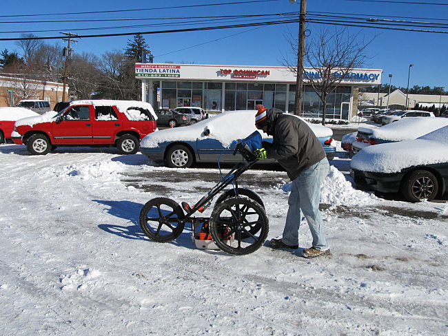
As a geophysical techniques, GPR has a relatively shallow exploration depth but provides relatively sharp visual images of buried objects. GPR does not usually exceed 5 feet in clays, and does not work well through puddled water (particularly salt water), snow, and like confounding conditions. However, GPR technology is ideal for locating buried USTs, wastes, and locating shallow subsurface disturbances (former excavated areas).
Really Technical Stuff for Science Buffs: The Physics Behind GPR Technology
GPR (Ground Penetrating Radar) functions primarily on one principle: refraction. Just as light (also electromagnetic waves) fractures as it enters one medium to another, so will the pulses send from your GPR antenna. A pulse will be send into the ground where it will contact a object made of a different material than the surrounding soil itself. These differences in dielectric properties (among them permittivity) will cause the pulse to diffract where a part of it will continue to move further into the ground – albeit at a changed angle – and some of it will reflect back to the GPR antenna. The more signal is send back the higher the power reading will be and thus a higher amplitude will be recorded. These amplitudes help us create a radargram.
These pulses (sinusoïdal waves) are usually of very short duration, about one to one and a half period long. This is used to determine the time it took to travel to the object, be reflected and travel back (two-way travel time or TWT) to the antenna. Imagine the pulse to be numbered as such that, for example, you send out five pulses you can also count five pulses that have been reflected. Now it is know how long each pulse has travelled as it is simply a matter of keeping track of the time between transmission and reception. These travel times are usually in the duration of nanoseconds (1 nanosecond is 1*10^-9 seconds). With a known two-way travel time (TWT) you can now also determine that depth at which it got reflected, provided that you know the approximate speed at which electromagnetic waves move through the sounded soil. Given a known speed ‘v’ in meters per nanosecond (m/ns) and a know TWT in nanoseconds then it is easy to see that depth ‘D’ in meters can be expressed as:
D = TWT / (2v)
If travel speed of a pulse through soil is unknown, it can be approximated as long as the relative dielectric permittivity ‘ε’ ‘ (read below) of the respective soil is known:
v ~ [ c / sqrt(ε’) ] * 10^-9
‘c’ being the speed of light in meters per second and sqrt being the square root of variable between brackets ().
Dielectric is only a indicative noun such as that you would call high saline water a dielectric. The values given from 5 to 81 are called (relative) dielectric permittivities in the unit of Farad per meter (F/m) with the symbol ε’. The permittivity of a medium describes how much of an electric field (more correctly, flux) is ‘generated’ per unit charge in that respective medium. It is one of the most important properties to know because it acts as a crucial factor in depth reach, pulse speed and spreading. As a rule of thumb, the higher the dielectric value of your sounded medium, the lower your resolution will be and the less of a penetration capacity your transmitted pulses will have.
Pure water itself has a relative dielectric permittivity value of about 80 F/m. Common water however can contain any number of dissolved chemicals and minerals. As such it’s permittivity can fluctuate quite a bit. It is also temperature sensitive and will usually show lower values at higher temperatures. On the otherhand ice, the solid form for water, continuously demostrates relativily low values of about 3 to 5 F/m. Keep this in mind.
Lastly one should also be wary of the soil’s conductive capacity. The higher the soil’s conductivity the lower your resolution and depth penetration will be. This is a result of the increased spreading of electromagnetic waves as they are being conducted through the soil. An analog to this would be to imagine water as it traves through a soil. The more pores the soil has the greater the potential for the water will be to spread. The water will reach the bottom but greatly spread out and with very few litres per square meter. On the otherhand if the soil had but one pore, all water present would have no choice but to move along that one pore towards the bottom.
The last important factor is the chosen center frequency (f) of your GPR system. Center frequency is the frequency of your sounded pulses. A frequency means how many periods a wave would contain per second if that wave would be transmitted continuous (in oposition of being transmitted pulses). The center part means it is part of a spectrum of frequencies. So a GPR with a center frequency of 500 MHz and a deviation of 20% might send out pulses with a frequency of 400 (lower bound) to 600 MHz (upper bound). If any object is to small to noticeably interfer with the sounded elektromagnetic waves, it will not produce a great enough reflection and as such will not be detected by your GPR. A rule of thumb says that an object must be atleast 1/4th the size of the wave length to be noticed. Formulated with object diameter ‘d’ and pulse wavelength ‘λ’ in meters:
d >= 0.25 * λ
Since the wavelength is a product of frequency and travelspeed it might also be expressed as a function of those two:
d >= 75 / [ f * sqrt(ε’) ]
Any object large enough to be spotted by pulses at center frequency will produce the highest possible resolution at the objects respective permittivity. objects large enough to be spotted by the lowest sounded frequency (lower bounds) might produce a noticeable radargram but it’s resolution will be lower the an object with comparable permittivity but a greater diameter.
* Resolution = The accuracy of the displayed dimensions on the radargram compared to the actual dimensions of the sounded object.